
Intechatandart

Electrical connectors

Connector R&D with a full package of design documentation (KD), technical specifications (TU) and process documentation (TD). Import substitution of foreign analogues, serial production of our own connector series.

Send a drawing
01
KD · TU · TD
full package
02
4 mo.
typical cycle
03
> 5,000
pcs per series
Anatomy

Inside the RS-32 connector

Key components: a bayonet-locking housing, dielectric insulator, gold-plated contact set and an IP67 seal.

CONNECTOR · CROSS-SECTIONCONNECTORS / 01
01 / Scope

What the service includes

01 / 04

Import substitution

Replacement of foreign analogues from a sample.

02 / 04

R&D for an analogue

Development work with a full documentation package.

03 / 04

Serial production

Our own connector series in serial production.

04 / 04

Support

Modifications and change management per plant regulations.

02 / Electrical and mechanical characteristics

Series and test parameters

Target values verified during PMI testing. Specific values per series — in the product's technical specifications (TU).

  • Contact resistance
    Baseline requirement
    ≤ 5 mΩ
    GOST 23784
  • Insulation resistance
    At normal conditions
    ≥ 1,000 MΩ
    GOST 14312
  • Dielectric strength
    Between contacts and housing
    1,000 V / 1 min
    GOST 14312
  • Operating voltage
    Depends on contact pitch
    up to 500 V DC
    Per TU
  • Operating current per contact
    Depends on ⌀ and material
    5 A / ⌀ 1.0 mm
    GOST 23784
  • Mating cycle life
    With inspection after the life test
    ≥ 500 cycles
    GOST 27.301
  • Mating / unmating force
    Depends on contact count
    ≤ 40 N
    Per TU
  • Vibration resistance
    Aviation and special equipment
    up to 20 g · 10–2,000 Hz
    GOST 16962
  • Shock
    Aviation and special equipment
    up to 150 g, 1 ms
    GOST 16962
  • Operating climate
    Standard version
    -60…+85 °C
    GOST 15150
  • Extended climate
    For special equipment
    -65…+125 °C
    GOST 15150
  • IP rating
    By version
    IP54 / IP67 / IP68
    GOST 14254
NB

The test program and procedures are agreed at the R&D stage. Test scope — standard per TU or extended per the customer's request.

03 / Materials

Materials and tolerance by size

Series
Design
Contacts
IP / climate
RS-32 (import substitution)
Cylindrical, bayonet
32, ⌀1.0 mm
IP67 · -60…+85 °C
Rectangular DSUB analogue
Rectangular, screw-lock
9 / 15 / 25
IP54 · -55…+85 °C
Aviation MIL-DTL analogue
Cylindrical, threaded
up to 128
IP68 · -65…+125 °C
High-current
Cylindrical, latch
1–4, ⌀5 mm
IP67 · up to 100 A / contact
PCB-mount
Rectangular, straight/angle
up to 200, 2.54 pitch
IP20 · -40…+85 °C
04 / Connector machinery

The equipment we work on

Machinery for manufacturing contact groups, housings and connector tooling.
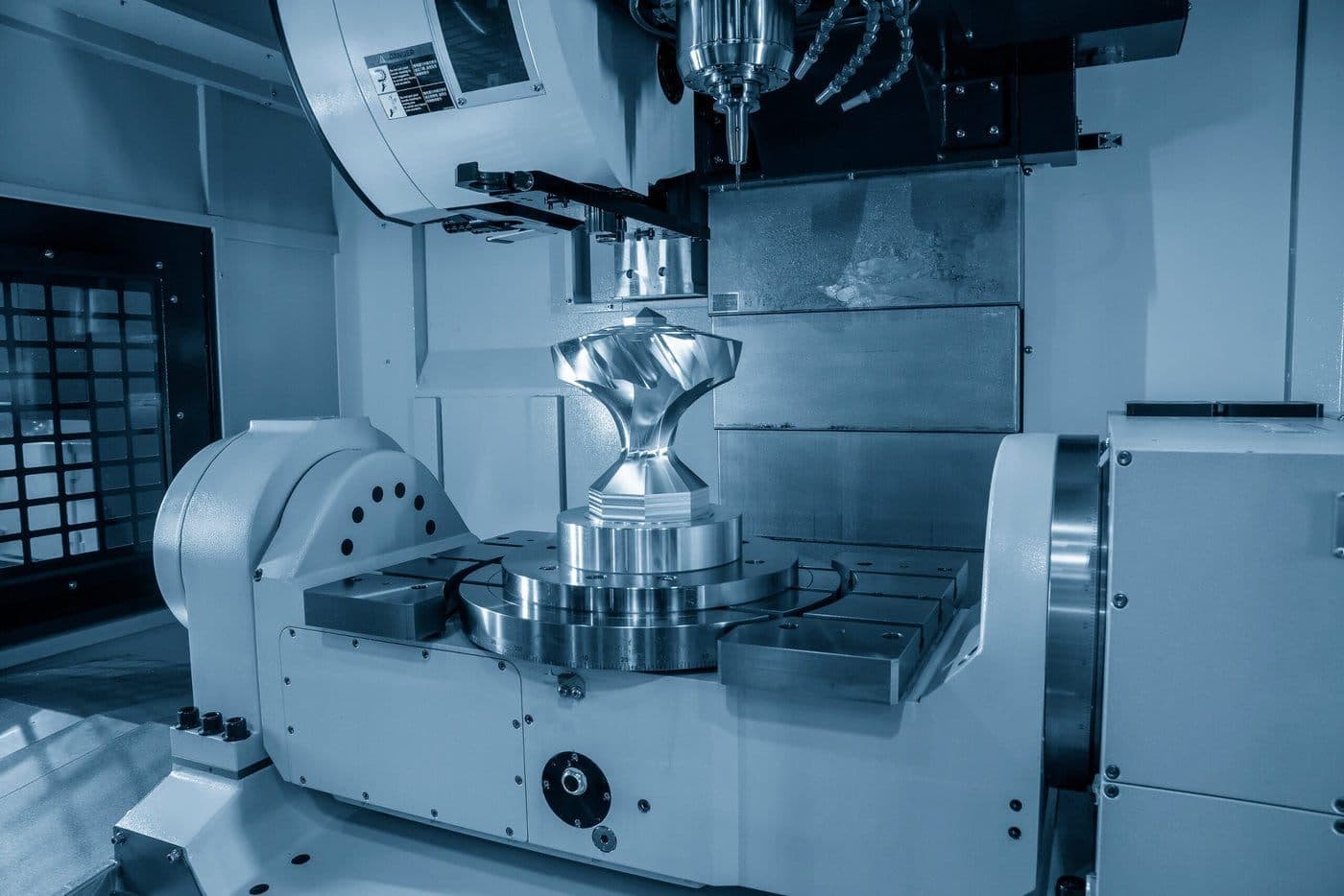
5-axis machining centre — Mazak VARIAXIS i-700
5-axis machining centre01 / 05
5-axis machining centre

Mazak VARIAXIS i-700

Complex geometries and undercuts in a single setup — no refixturing.
Work envelope
700 × 700 × 500 mm
Spindle
up to 12,000 rpm
Repeatability
±0.003 mm
Tool magazine
30 tools
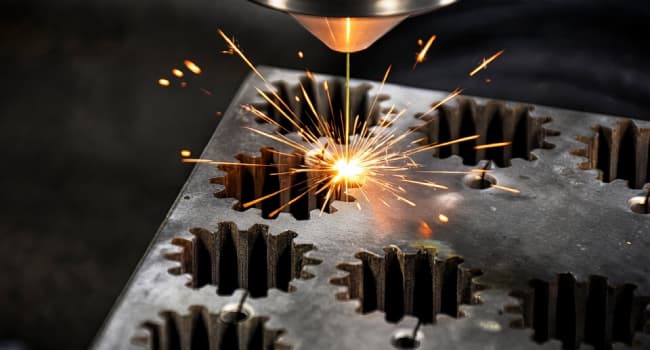
Wire EDM — Sodick AQ535L
Wire EDM02 / 05
Wire EDM

Sodick AQ535L

Contour cutting of complex profiles and internal contours with IT7 tolerance.
Work envelope
500 × 350 × 250 mm
Thickness
up to 250 mm
Wire
⌀ 0.1–0.3 mm
Accuracy
±0.003 mm
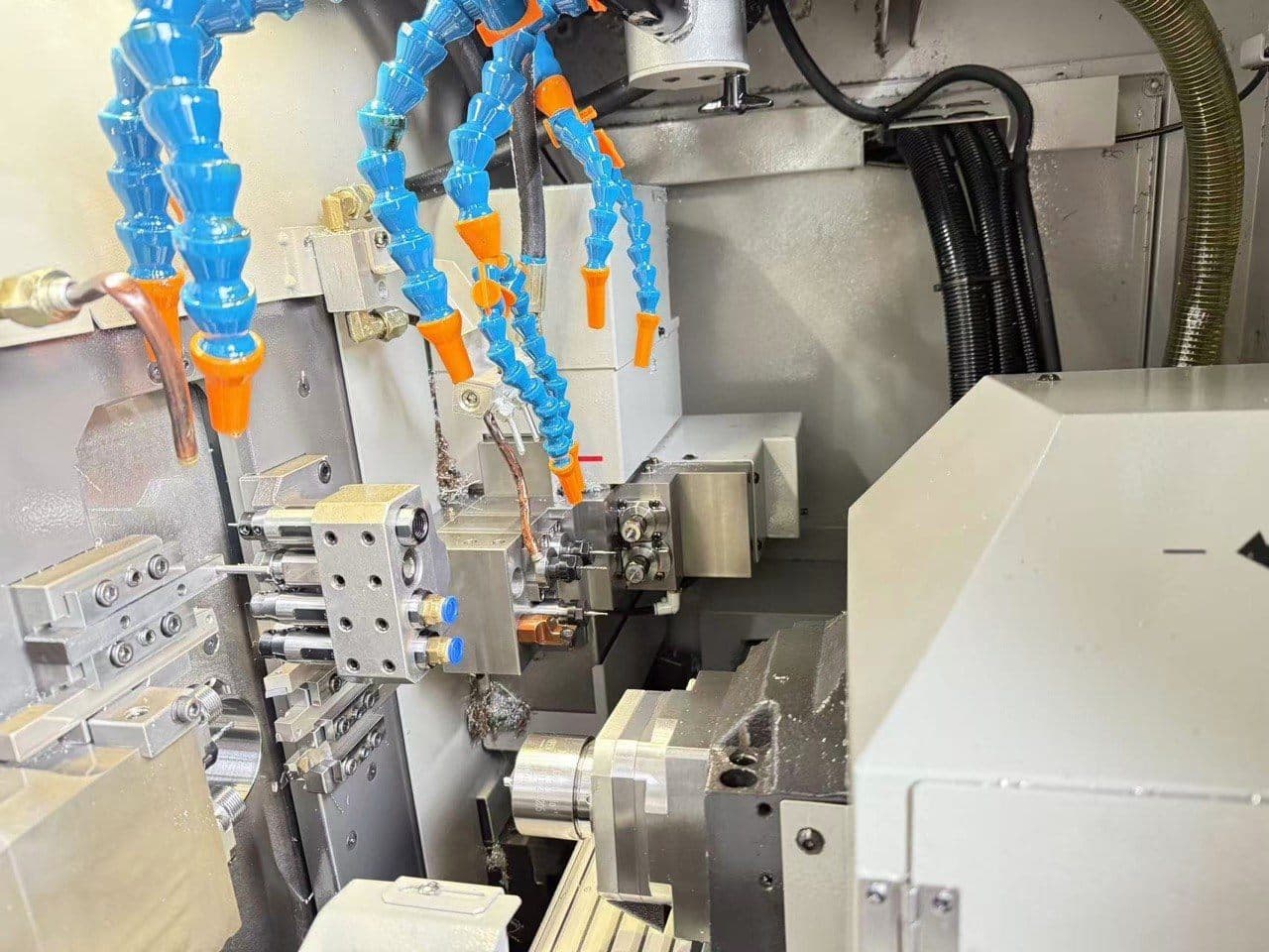
Swiss-type lathe — Tsugami B0206-V
Swiss-type lathe03 / 05
Swiss-type lathe

Tsugami B0206-V

Serial turning of contacts and small precision parts from bar stock in one setup.
Bar ⌀
up to 20 mm
Spindles
10,000 / 12,000 rpm
Tools
27 stations
Control
FANUC 0i-TF Plus
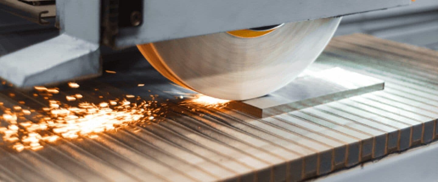
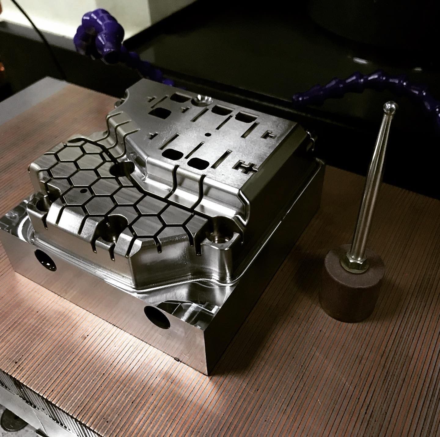
Surface grinder — Okamoto ACC-1224ST
Surface grinder04 / 05
Surface grinder

Okamoto ACC-1224ST

Plates, bases and guides — after heat treatment.
Work table
600 × 300 mm
Accuracy
±0.002 mm
Surface finish
Ra 0.2 µm
Magnetic table
Polishing station — Manual + diamond paste
Polishing station05 / 05
Polishing station

Manual + diamond paste

Surface finishing to a mirror finish and sealing joints.

Surface finish
Ra down to 0.02 µm
Inspection
SJ-410 profilometer
For steels
S136, 2316, 718H
Application
Optical, medical plastics
NB

Equipment class; the exact lineup and serial numbers — on request under NDA.

05 / Electrical testing

How we test connectors

Contact resistance, insulation, dielectric strength, mating cycle life. Accredited laboratory — at a partner.

Primary instrument
Contact resistance test setup
MIKO-9 micro-ohmmeter
Range
10 µΩ – 200 Ω
Accuracy
0.1%
Standard
GOST 23784
Application
Every batch
Insulation test setup
GW Instek GPT-9803
Voltage
up to 5 kV AC / 6 kV DC
Leakage current
0.1 mA – 100 mA
Test modes
GOST 14312
Application
Hipot test
Life test setup
Mating cycle test rig
Cycles
up to 10,000
Speed
up to 30 cycles/min
Inspection
resistance after the life test
Climatic chamber (partner)
ESPEC SH-262
Temperature
-70…+180 °C
Humidity
20…98 %
Standards
GOST 15150 / IEC 60068
06 / R&D checklist

8 rules to start connector R&D

What is needed to start import substitution work. The more detail up front — the fewer approval iterations.

Rule 01 / 08

Reference sample

At least 2 working pcs + 1 for destructive analysis

For reverse engineering and parameter verification.

Rule 02 / 08

Electrical parameters

Operating U, I, contact R, insulation R, mating cycle life

If parameters are unavailable — we take them from the analogue and agree.

Rule 03 / 08

Application and environment

Climate, IP, vibration / shock, chemical environment

Defines the choice of materials and the test program.

Rule 04 / 08

Mating dimensions

Contact pitch, contact ⌀, housing envelope, mounting

We hold these dimensions within ±0.05 mm for compatibility.

Rule 05 / 08

Contact plating

Au — premium · Ag — standard · Sn — volume · Ni — underlayer

Affects life, contact resistance and price.

Rule 06 / 08

Accuracy class and tolerances

Contacts ±0.005 mm · housing ±0.05 mm · h7/H7 fits

Conformance to the foreign analogue is confirmed by measurement.

Rule 07 / 08

Volumes and production run

Pilot batch — 50 pcs · series — from 500 pcs per quarter

Series size drives the process choice (moulding vs stamping).

Rule 08 / 08

Marking and certification

Marking per TU · certification in the customer's system / GOST R

Certification is carried out in accredited laboratories.

07 / R&D documentation

What to send to start R&D

To start connector R&D, a reference sample plus a specification is enough. Additional data speeds up approvals.

Minimum drawing content
DRAWING / EXAMPLE
  • 01Reference sample (physical) for measurement
  • 02Operating electrical parameters (U, I)
  • 03Climatic version (T, humidity)
  • 04IP and vibration resistance requirements
  • 05Mating dimensions
  • 06Contact plating and housing material
  • 07Batch marking and packaging
  • 08Volumes (pilot batch + series)
3D formats
06
  • ·STEP / STP (if available)
  • ·IGES / IGS
  • ·X_T (Parasolid)
  • ·SLDPRT / PRT
  • ·Reference sample (physical)
  • ·Electrical schematic (E3)
2D drawings
03
  • ·DWG / DXF (if design docs for the analogue exist)
  • ·PDF datasheet of the foreign analogue
  • ·Sketch with mating dimensions
08 / Plating and finishing

Contacts and housing: platings

Contacts — electroplating chosen by life and cost. Housings — finish for the operating environment.

Through trusted partners
Electroplating, heat treatment and complex coatings go to specialised shops under a defined procedure.
06
  • Contact silver plating (Ag)
    GOST 9.301-86
    3–9 µm · standard
  • Contact gold plating (Au)
    ASTM B488
    0.5–3 µm over Ni underlayer
  • Contact tin plating (Sn)
    GOST 9.301-86
    5–15 µm · solderable
  • Nickel underlayer
    GOST 9.301-86
    2–6 µm under Au / Ag
  • Housing chromating (Al)
    GOST 9.301-86
    Cr3+ / Cr6+ as required
  • Housing anodising
    GOST 9.301-86
    8–25 µm, black / colour
10 / Documentation

What we deliver

A complete documentation package, ready for certification in the customer's system or under GOST R.

Design documentation (full set)Technical specifications (TU)Process documentationTest reports (electrical, climatic, mechanical)Material certificate (brass / dielectric)Test program and procedures (PMI)
11 / FAQ

Frequently asked questions

01How long does a full R&D cycle take?

The typical cycle is 3–4 months from receiving the reference sample to series launch. With an extended test program — up to 6 months.

02What documentation do you prepare?

The full package: design documentation, technical specifications, process documentation, test program, test reports (climatic, mechanical, electrical). Delivered electronically and as signed hard copies.

03Can you confirm interchangeability?

Yes — testing of mating dimensions, contact resistance and mating cycles. The report is attached to the batch.

04What contact groups are available?

⌀ 1.0 / 1.5 / 2.0 / 3.0 / 5.0 mm. Material — brass LS59-1, bronze BrB2 with Au / Ag / Sn / Ni electroplating.

05Certification for aviation / special equipment?

We prepare documentation for the customer's certification system. Testing in accredited laboratories — via partners.

Inquiry

Send a drawing —
we'll quote within 24 hours

Fill in the form or contact us directly — any channel works.

ПН–ПТ · 09:00–18:00 · МСК
Enquiry form