
Intechatandart

Production tooling

Casting moulds, stamping dies and injection moulds from a drawing or a reference sample. A turnkey cycle — from design to commissioning at the customer's site.

Send a drawing
01
> 200,000
cycles
02
±0.02 mm
moulding accuracy
03
3–6 mo.
manufacturing cycle
Anatomy

What an injection mould is made of

The standard set of plates, cavity and core inserts, cooling and ejection systems. Steel grade and tool life are specified at the design stage.

MOLD · CROSS-SECTIONTOOLING / 01
01 / Scope

What the service includes

01 / 04

Casting moulds

For plastics and non-ferrous alloy casting.

02 / 04

Stamping dies

Die sets for serial production.

03 / 04

Injection moulds

For injection moulding machines.

04 / 04

Process routing

With gauges and process parameters for the customer's line.

02 / Accuracy and Ra

Tolerances and surface finish by tooling operation

Tolerances of forming surfaces and mirror finishing. By default — general mould tolerances per GOST 22085-76.

  • Finish HSC milling
    Forming surfaces on the 5-axis
    IT8–IT7
    0.8
  • Wire EDM
    Punches, contour operations
    IT7
    1.6
  • Sinker EDM (rough)
    Deep cavities, ribs
    IT9
    3.2
  • Sinker EDM (finish)
    Finish EDM of cavities
    IT7–IT6
    0.8
  • Surface grinding
    Plates, bases
    IT6
    0.4
  • Profile grinding
    Guides, mating surfaces
    IT6–IT5
    0.2
  • Diamond paste polishing
    For transparent plastics, optics
    0.1–0.02
  • Honing
    Cylindrical cooling channels
    IT6
    0.1
  • EDM finish (electrolytic)
    After the main EDM
    IT6
    0.4
NB

Mirror polishing (Ra ≤ 0.05 µm) is a separate manual operation and requires S136 or 2316 steels.

03 / Materials

Materials and tolerance by size

Steel
HRC
Application
Life
P20 (1.2311)
30–34
Basic plastic moulds
≥ 500,000 cycles
718H (1.2738)
32–38
Heavy-duty moulds
≥ 1,000,000 cycles
H13 (1.2344)
44–52
Al / Zn die casting
≥ 250,000 cycles
S136 (1.2083)
50–54
Transparent plastics, medical
≥ 1,000,000 cycles
Cr12MoV / D2
58–62
Blanking and forming dies
Serial-grade life
XW-42 (Uddeholm)
58–62
Progressive dies
High life
04 / Tooling machinery

What we make tooling on

Machinery for forming inserts, plates, guides and finish work.
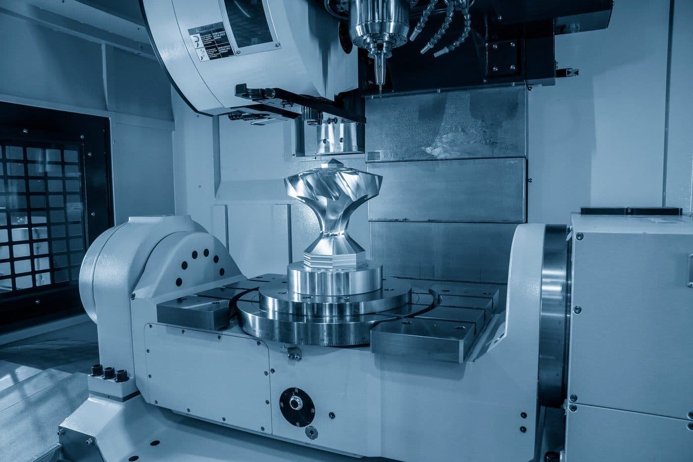
5-axis machining centre — Mazak VARIAXIS i-700
5-axis machining centre01 / 05
5-axis machining centre

Mazak VARIAXIS i-700

Complex forming surfaces in a single setup — no refixturing.
Work envelope
700 × 700 × 500 mm
Spindle
up to 12,000 rpm
Repeatability
±0.003 mm
Tool magazine
30 tools
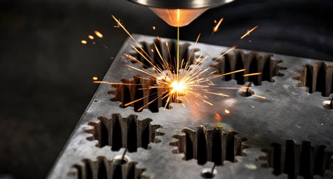
Wire EDM — Sodick AQ535L
Wire EDM02 / 05
Wire EDM

Sodick AQ535L

Contour cutting of die punches and cavities with IT7 tolerance.
Work envelope
500 × 350 × 250 mm
Thickness
up to 250 mm
Wire
⌀ 0.1–0.3 mm
Accuracy
±0.003 mm
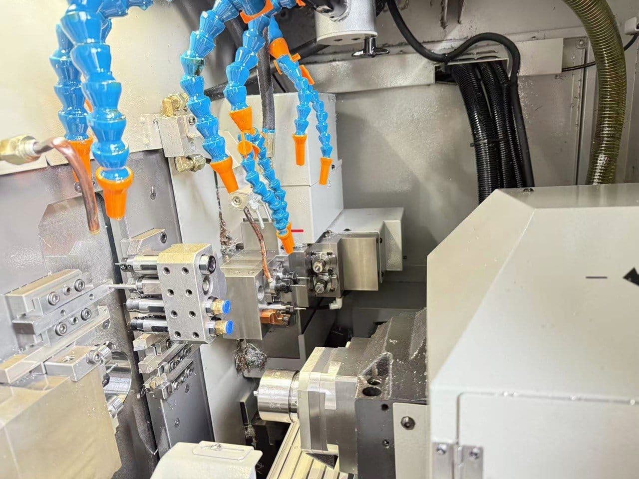
Swiss-type lathe — Tsugami B0206-V
Swiss-type lathe03 / 05
Swiss-type lathe

Tsugami B0206-V

Serial turning of small precision parts from bar stock — the full cycle in one setup.
Bar ⌀
up to 20 mm
Spindles
10,000 / 12,000 rpm
Tools
27 stations
Control
FANUC 0i-TF Plus
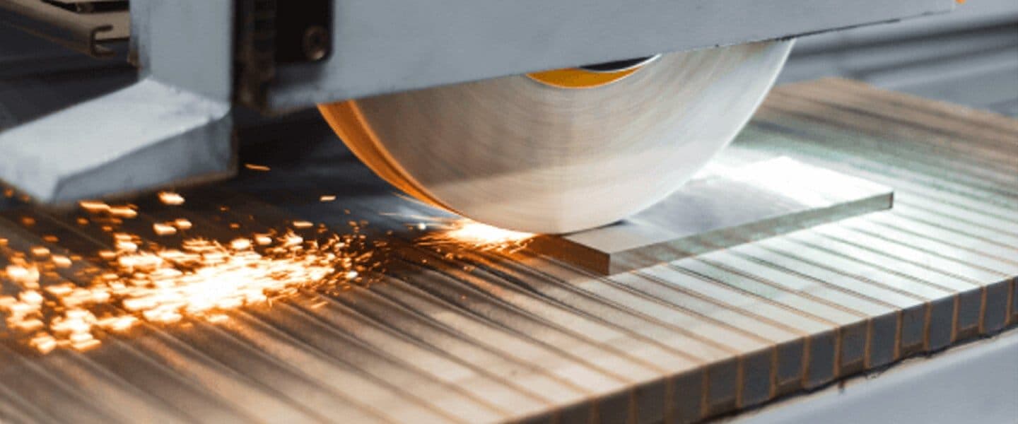
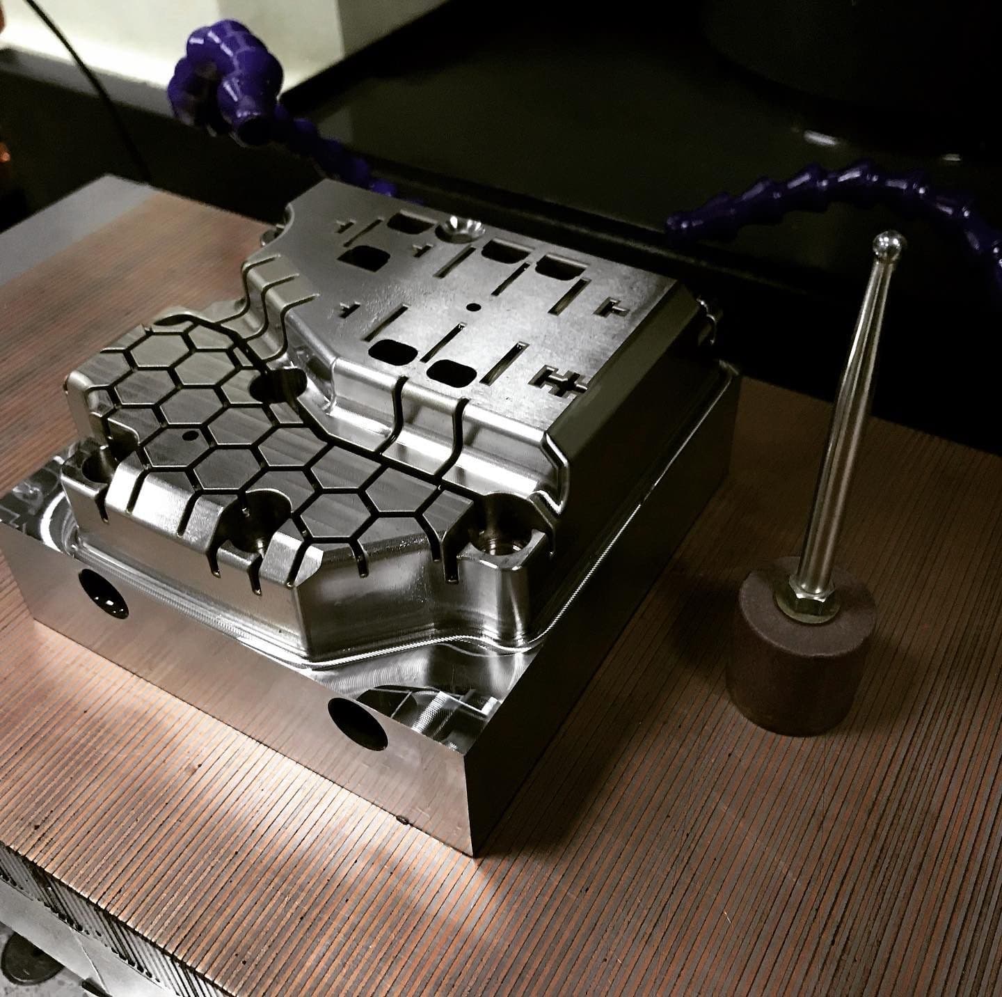
Surface grinder — Okamoto ACC-1224ST
Surface grinder04 / 05
Surface grinder

Okamoto ACC-1224ST

Plates, bases and guides — after heat treatment.
Work table
600 × 300 mm
Accuracy
±0.002 mm
Surface finish
Ra 0.2 µm
Magnetic table
Polishing station — Manual + diamond paste
Polishing station05 / 05
Polishing station

Manual + diamond paste

Finish work on forming surfaces to a mirror finish and sealing joints.

Surface finish
Ra down to 0.02 µm
Inspection
SJ-410 profilometer
For steels
S136, 2316, 718H
Application
Optical, medical plastics
NB

Equipment class; the exact lineup and serial numbers — on request under NDA.

05 / Forming surface metrology

How we measure tooling

CMM — overall dimensions. Optical 3D scanner — forming surfaces and complex cavities referenced to the CAD model.

Primary instrument
Coordinate measuring machine
Mitutoyo Crysta-Apex S 776
Volume
700 × 700 × 600 mm
MPE-E
(1.5 + L/333) µm
Probe
Renishaw scanning
Software
MCOSMOS / GeoMeasure
Optical 3D scanner
Hexagon AICON SmartScan
Accuracy
down to 5 µm
Scanning field
500 × 500 mm
CAD comparison
ColorMap deviation map
For moulds and cavities
Surface roughness tester
Mitutoyo SJ-410
Rz range
350 µm
Resolution
0.01 µm
Parameters
Ra, Rz, Rt, Rq
Application
Polished surfaces
Hardness tester
Mitutoyo HR-320MS
Scales
HRC, HV, HB
Inspection
HRC verification after heat treatment
06 / DFM for tooling

8 product design rules for tooling

A checklist before sending the product drawing. These points have the biggest impact on lead time, mould life and moulding / stamping quality.

Rule 01 / 08

Draft angles

1° for plastics · 0.5° for metals · from 3° for textured surfaces

Without draft — sticking on ejection, cavity wear and marks on the product.

Rule 02 / 08

Uniform wall thickness

Thickness variation ≤ 50% · optimum 2–4 mm for plastic

Abrupt transitions → warping, sink marks, hidden stresses.

Rule 03 / 08

Fillet radii

Internal R ≥ 0.3 mm at wall joints · external R ≥ ⅓ of wall thickness

Sharp corners concentrate stress; the mould fails sooner.

Rule 04 / 08

Runner system

Hot runner — for series >50k · cold runner — for short runs

Runner balancing is critical for multi-cavity moulds.

Rule 05 / 08

Ejection system

Min. 3 ejection points, symmetrical · ejector ⌀ 3–8 mm

Asymmetry → skewing; on large areas — blade ejectors.

Rule 06 / 08

Cooling channels

⌀ 8–12 mm · distance to cavity ≥ 1.5× channel ⌀ · pitch 3× ⌀

Unbalanced cooling → warping and longer cycles.

Rule 07 / 08

Parting line

In the part plane where possible · draft away from the parting line

A complex parting line makes the mould more expensive to make and tune.

Rule 08 / 08

Material shrinkage

ABS 0.5% · POM 1.8% · PA6 1.2% · PC 0.7%

Shrinkage is built in at the mould CAD modelling stage.

07 / Drawings and formats

What to send for tooling

We accept product CAD formats and mould requirements. Shrinkage calculation and mould CAD refinement are done on our side.

Minimum drawing content
DRAWING / EXAMPLE
  • 01Plastic / metal grade of the product with shrinkage stated
  • 02Volume and production run (for tooling steel selection)
  • 03Product surface finish (Ra by zone)
  • 04Tolerances of key product dimensions
  • 05Surface texture (Mold-Tech / VDI 3400)
  • 06Marking / branding zones on the product
  • 07Ejection points (if there are requirements)
  • 08Parting line (if there are requirements)
3D formats
06
  • ·STEP / STP (the product, preferred)
  • ·IGES / IGS
  • ·X_T (Parasolid)
  • ·SLDPRT (SolidWorks)
  • ·PRT (NX / Creo)
  • ·Mould flow analysis data — if available
2D drawings
03
  • ·DWG / DXF
  • ·PDF of the product drawing with the current revision
  • ·Sketch + 3D model — DFM to be agreed
08 / Heat treatment and finishing

Heat treatment, coatings and finish

Hardening and nitriding — via partners with years of experience in tool steels. Polishing and mirror finishing — in-house.

Through trusted partners
Electroplating, heat treatment and complex coatings go to specialised shops under a defined procedure.
06
  • Hardening + tempering
    GOST 4543 / DIN EN 10052
    HRC 30–62 depending on the steel
  • Nitriding
    GOST 24622 / DIN 17211
    Depth 0.2–0.5 mm, HV 800–1000
  • TiN / CrN coating (PVD)
    DIN 50320
    Thickness 2–4 µm, +50% life
  • Chrome plating
    GOST 9.301-86
    Anti-corrosion, up to 25 µm
  • Chemical oxidising of steel
    GOST 9.305-84
    Protective black
  • Bluing
    For non-working surfaces
10 / Documentation

What we deliver

We hand over the full package with the tooling: documentation, process parameters, maintenance schedule and a set of spare consumables.

Tooling design documentation3D mould model (STEP)Moulding / stamping process cardTrial acceptance reportSteel and heat treatment certificatesMaintenance card
11 / FAQ

Frequently asked questions

01What tooling materials do you use?

P20, 1.2738 (718H), H13 (1.2344), S136 (1.2083) for moulds; Cr12MoV, XW-42 — for stamping dies. Selected by required life and product material.

02What is the maximum mould size?

Mould envelope — up to 600 × 600 × 500 mm. For larger moulds we involve partners with heat-treatment furnaces and heavy-duty overhead cranes.

03Do you guarantee tooling life?

The guarantee is stated in the contract, typically 100,000 cycles for P20 moulds and 250,000+ for heavy-duty ones. We support it with a maintenance schedule.

04Support after tooling handover?

Scheduled maintenance, fine-tuning after the first batches, repair on wear. Warranty period — from 12 months.

05Do you take moulds for modernisation?

Yes, we rework existing moulds: cavity/punch replacement, re-etching, runner system changes, cooling improvements.

Inquiry

Send a drawing —
we'll quote within 24 hours

Fill in the form or contact us directly — any channel works.

ПН–ПТ · 09:00–18:00 · МСК
Enquiry form